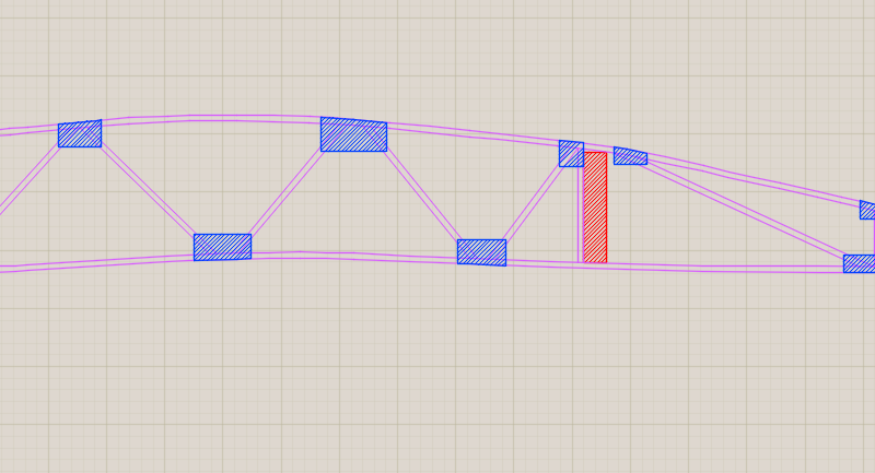
EDIT: 2/20/2024 – I cannot recommend following my example below. I printed this CAD drawing onto multiple sheets of paper, and carefully measured and taped them together to make my full-size rib layout. Unfortunately, my laser printer produced slightly trapezoidal printings – unlike the perfect rectangle that the area inside the margins should be. This caused a significant cumulative error. The vertical members next to the spars were out of parallel by about 1/8″ of an inch at their extremes. I have chosen to partially rebuild my ribs to correct this error.
I would have been well advised when I did this back in 2017 to simply use a long straight edge as my X axis, and a construction square as a sliding Y axis, and plot the points in that way. I used this method on my fuselage layout, and was very happy with the results. The same technique could be applied to the ribs. It is as accurate as 1/2 the smallest markings on the straight edge and square. The whole CAD layout is unnecessary.
As to the gussets, they could be grouped into pieces of similar width, all cut at once out of strips of plywood, glued on, and then trimmed with a router to fit the profile of the rib.
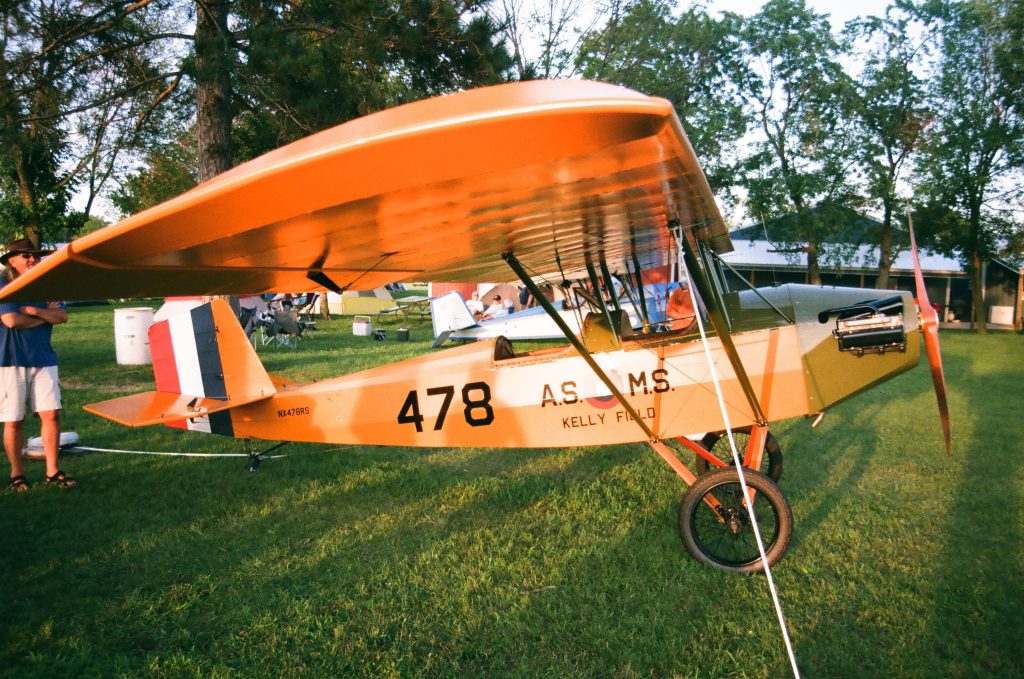
The first goal after receiving plans for the homebuilt airplane was to draw the wing ribs in AutoCad. The drawings for Mr. Pietenpol’s The Improved Air-Camper date back to 1934. His grandson Andrew Pietenpol still sells them on the family-operated website: www.pietenpolaircraftcompany.com.

While full-sized wing rib printings are available, I chose to conserve the $15, and simultaneously become more familiar with the design. Several surprising points became evident to me. First, the bottom of the airfoil is not flat. Upon discussion with a friend, he forwarded a link to me which compares lift and drag of various comparable aircraft. The Pietenpol has undercamber similar to the Sopwith Camel, which hearkens back to earlier days of aviation where much study had arisen from birds. Undercamber and higher angle of attack is more like flying with flaps; more lift, but more drag. Secondly, the dimensions given are adequate, but sparse. The airfoil is carefully dimensioned, as well as critical interfaces like slots for the spars. But truss members and gussets are left up to interpretation. Thirdly, the drawings are downright beautiful. Anyone who builds a Pietenpol almost certainly contains within them a nostalgic streak, and these drawings resonate harmoniously with an appreciation for early tech. They are of the style and genre of old mechanical how-to’s for boys. The designs themselves are, while somewhat unfeatured, still simple, strong, and robust.

The old-timey feel about the project however has put me at a thought-provoking crossroads. On the one extreme, I could restrict myself to hand tools, pencils, and graphing compasses in order to fully appreciate the historicity of the project. On the other extreme, I could design every part in CAD, and get it CNC’d (I do have access to such tools at my school) and operate with the mechanical precision offered by modern machining.

My choice however, has been to take what I feel to be the truly authentic modern interpretation of Mr. Pietenpol’s designs. My goal is to KISS (Keep It Simple, Stupid) this project, and apply the same principles of robustness and simplicity in my construction that Mr. Pietenpol used in his design. He used what he had available, and whatever was most practical. I intend to do the same.
Wistful dreams of Airplane Picnics with my wife, or week-long camping trips hopping between small Midwestern grass strips reside in my cognition thereby mandating that weight should also be optimized in order to accommodate 300lbs of passengers, and a minimal assortment of gear and/or fuel.
Thus the two primary variables to optimize are simplicity and performance. And those, unless I be otherwise convinced, will be my guidelines of construction.
