There’s been a lot of electronics work that’s gone into this project. And it’s not over yet by any means. But here’s some interesting pictures explaining how I went about some of it.
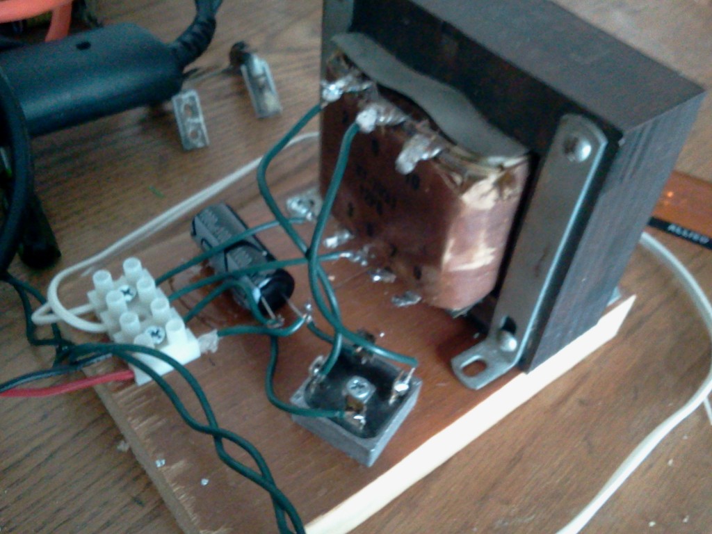
That’s the 50vDC Power Supply. For the flippers and a few other soleniods. It’s really simple. Transformer, Bridge Rectifier, Enormous Capacitor.
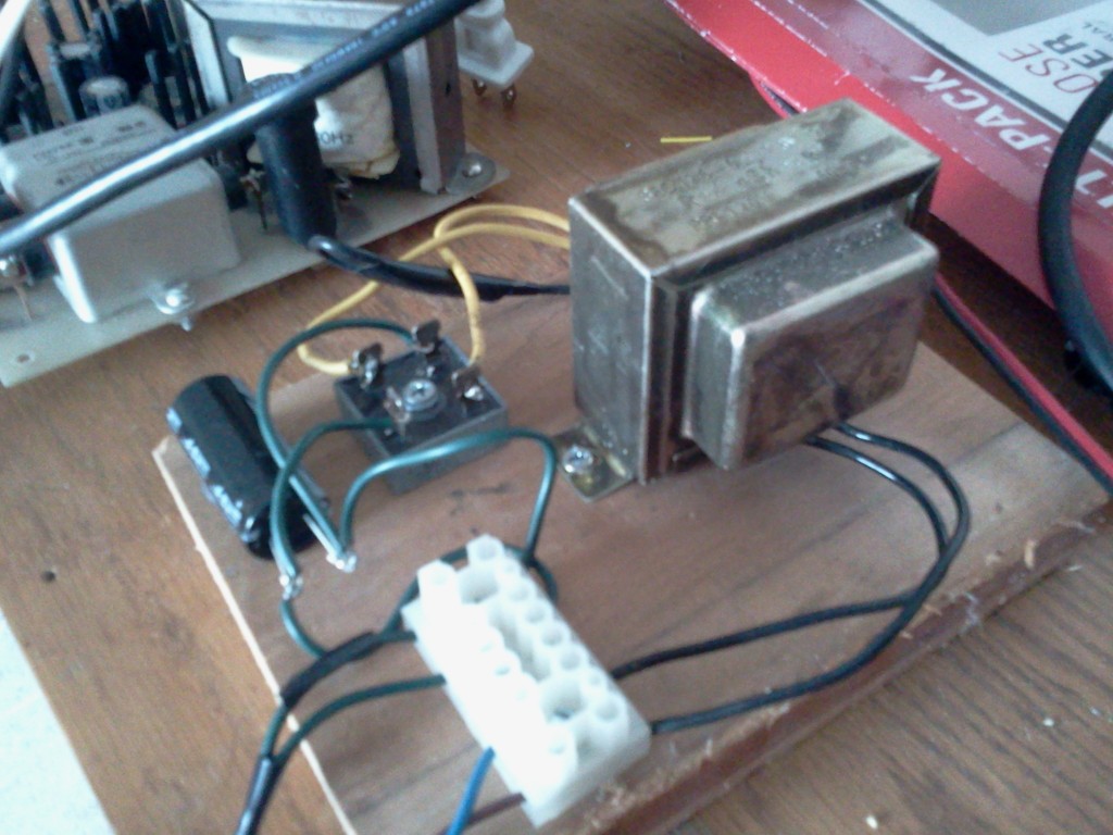
Here is the smaller 25vDC Power Supply. Similar construction, smaller Transformer.
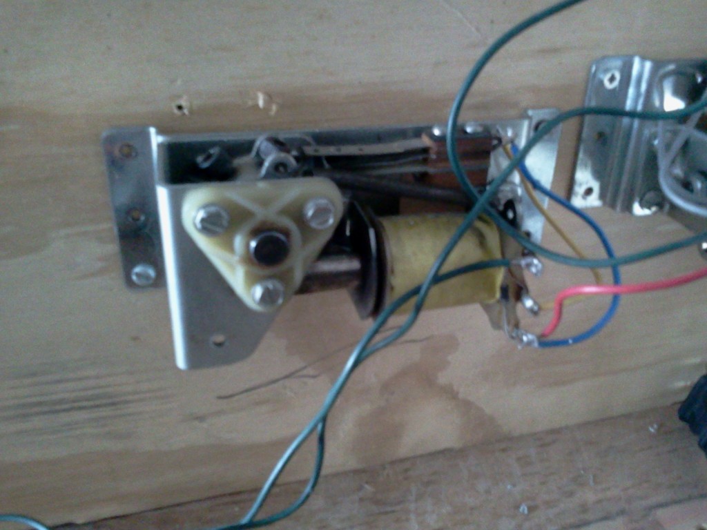
A wired Flipper Assembly. Notice the triple contacts on the soleniod, and the EOS (End Of Stroke) switch.
Right now, I have the flippers hard-wired through a high-current push button switch, but I’ll probably have to put in a relay for the real Pinball Buttons.
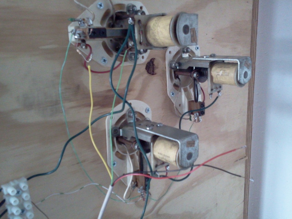
Bumpers installed in the prototype playfield. 25v doesn’t seem to give them much kick, but perhaps they simply need to be on longer.
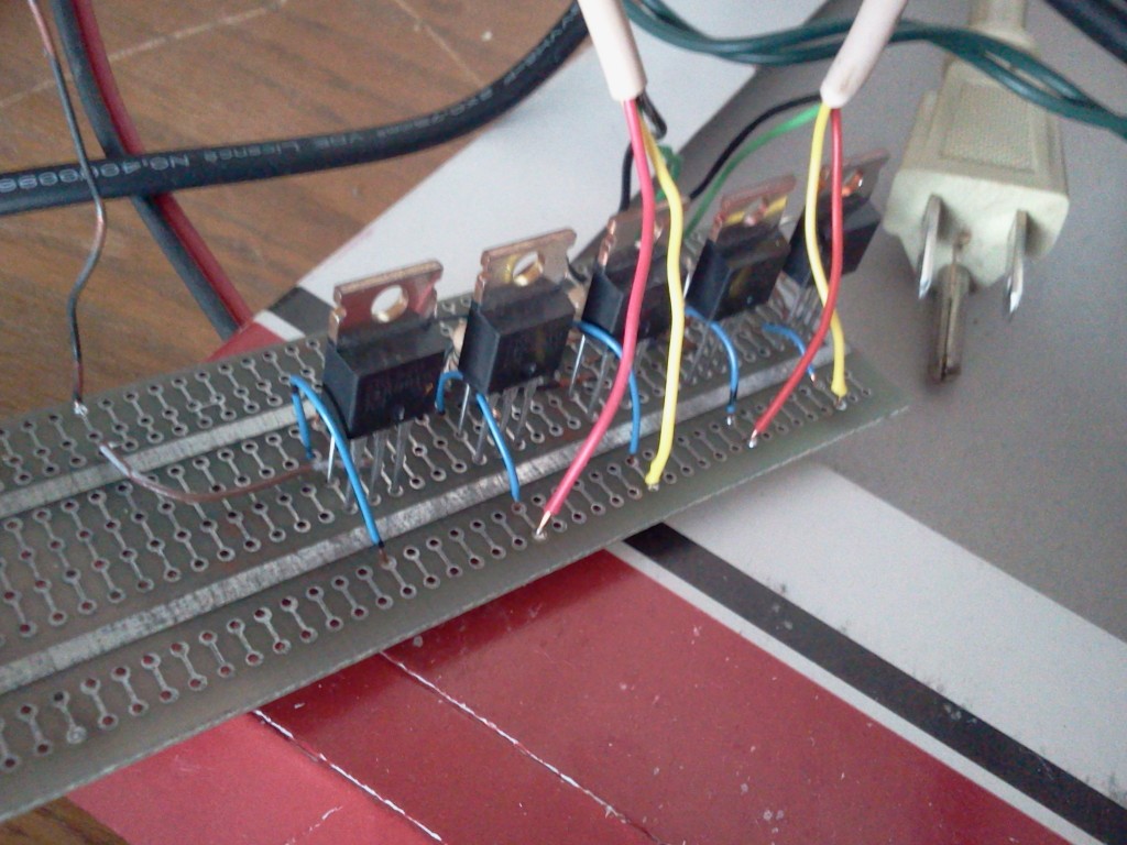
The MOSFET (Metal Oxide Semiconducter Field Effect Transistor) board that switches 25v for the solenoids with the 5v signal from the bumper’s switches.
That’s it for now. If you have more questions, leave a comment below, or tweet at me @marktbaldridge. And check back soon! 🙂
You probably want to add 1N4001 or 1N4004 diodes (cathode towards supply voltage) in parallel with all your solenoids and relays, so you don’t blow up your driver transistors/FETs with the negative voltage spike when they shut off.
Yes. In fact, those are built in to the solenoid assemblies. Pinball coils come with diodes, so I always forget to include them in my schematics. 😛 You can sort of see them in the pictures. Right on the plastic piece of the coil.