Well, it’s been forever since I’ve updated this site. Things have been happening, so hopefully we can get up to speed pretty quickly.
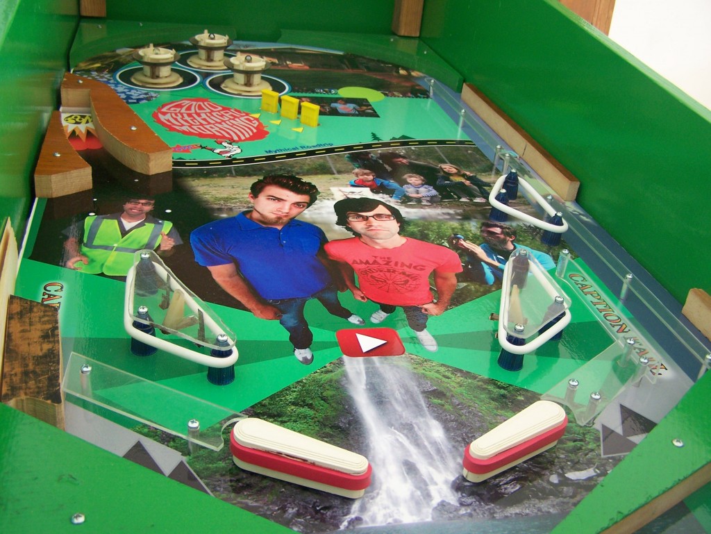
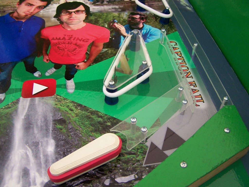
So, that’s what the playfield is currently looking like. Pretty much everything you see there works.
Slingshots, Bumpers, DropTargets, flippers, ball return, shooter, flipper buttons, the works.
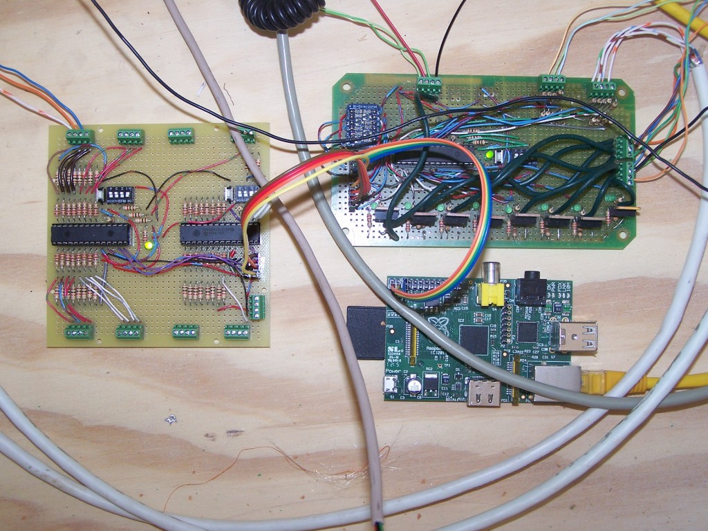
Currently, there’s three boards that make up the “brains” There’s the RaspberryPi, and two boards cortroled on an I2C buss.
The board top left is my input board. Two MCP23017 chips are used as I/O expanders on an I2c buss. Only the left chip is fully wired up at this point.
The top right board is my original control board.
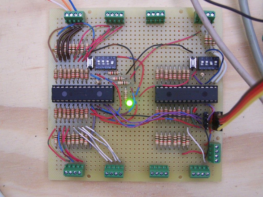
A close up of the board. Two MCP23017’s. Each chip has 16 inputs. I installed pull-down and buffer resistors on each input.
Each chip can be set to a specific I2C address using the dip switches. Anything from 0x20 to 0x27.
With two chips on that board, I have a grand total of 32 Inputs.
Here’s the ball return assembly. A jerry-rigged thing, but it works like a charm. 🙂
A cabinet kicker assembly is used to shove the ball back up into the shooter lane, and a trimmed down leaf switch makes a good sensor.
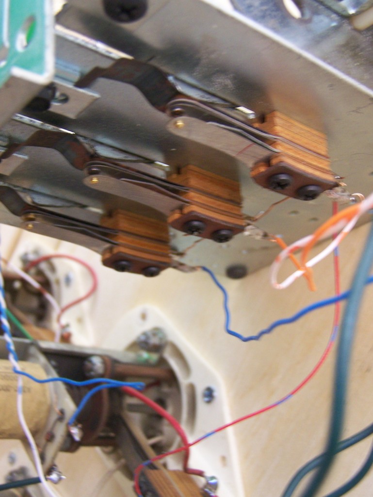
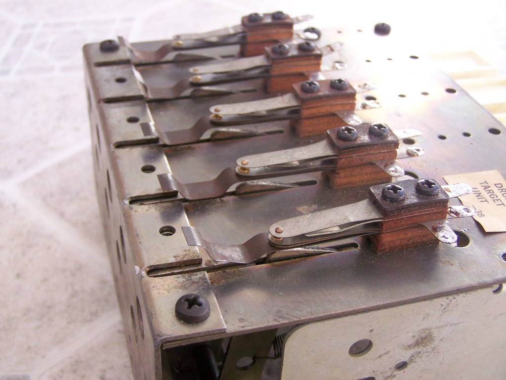
It’s a bit blurry, but you can see the leaf switches for each drop target wired up.
Some people would say USE A SWITCH MATRIX!!! But in all honesty, that seemed like more trouble than it was worth to me.
My dad’s got a bunch of twisted pair snakes laying in our basement that I’ve been using. It’s worked pretty well so far…
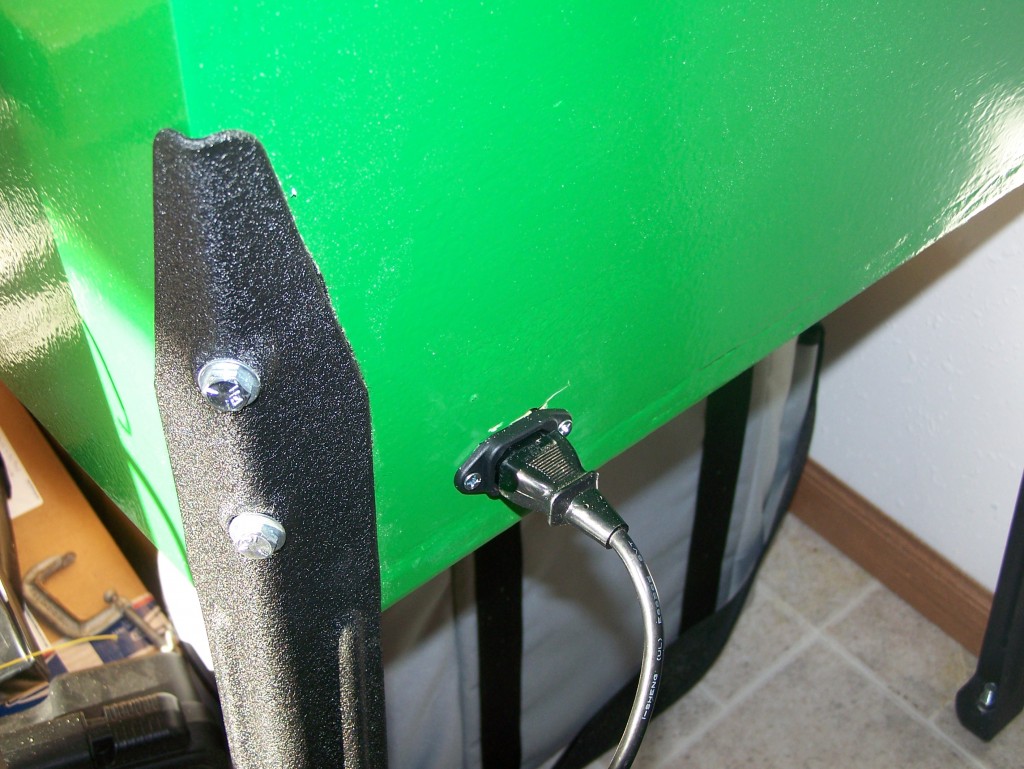
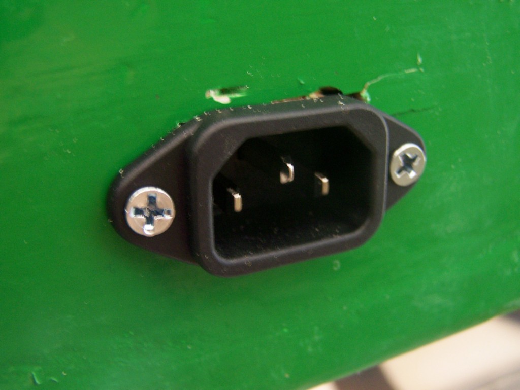
There’s an AC plug installed. So, my pinball machine can use a regular AC cord! 😀
The cut with the gig-saw got a bit messy. Oh to have a CNC and good CAD!! :'(
I’ll probably be able to fix that somehow.
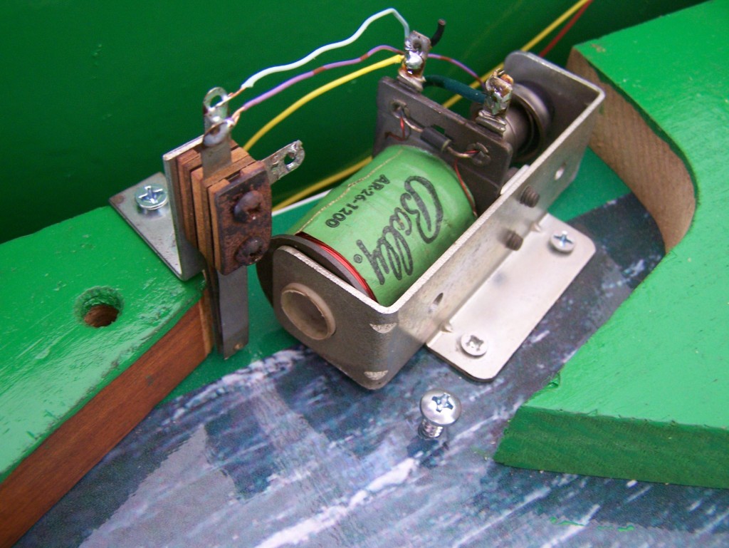
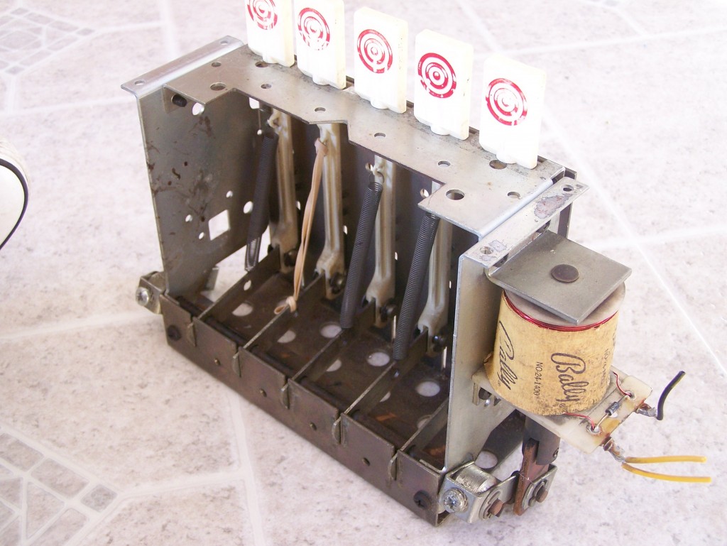
I got a box of pinball junk on eBay for about $20. This drop target assembly came with it, but was pretty beat up.
Here it is rebuilt. Works like a charm now. 🙂
All the leaf switches had been mashed, and because of that, the targets wouldn’t drop.
So I disassembled each one, and straightened out the metal.
Seems to work really well now.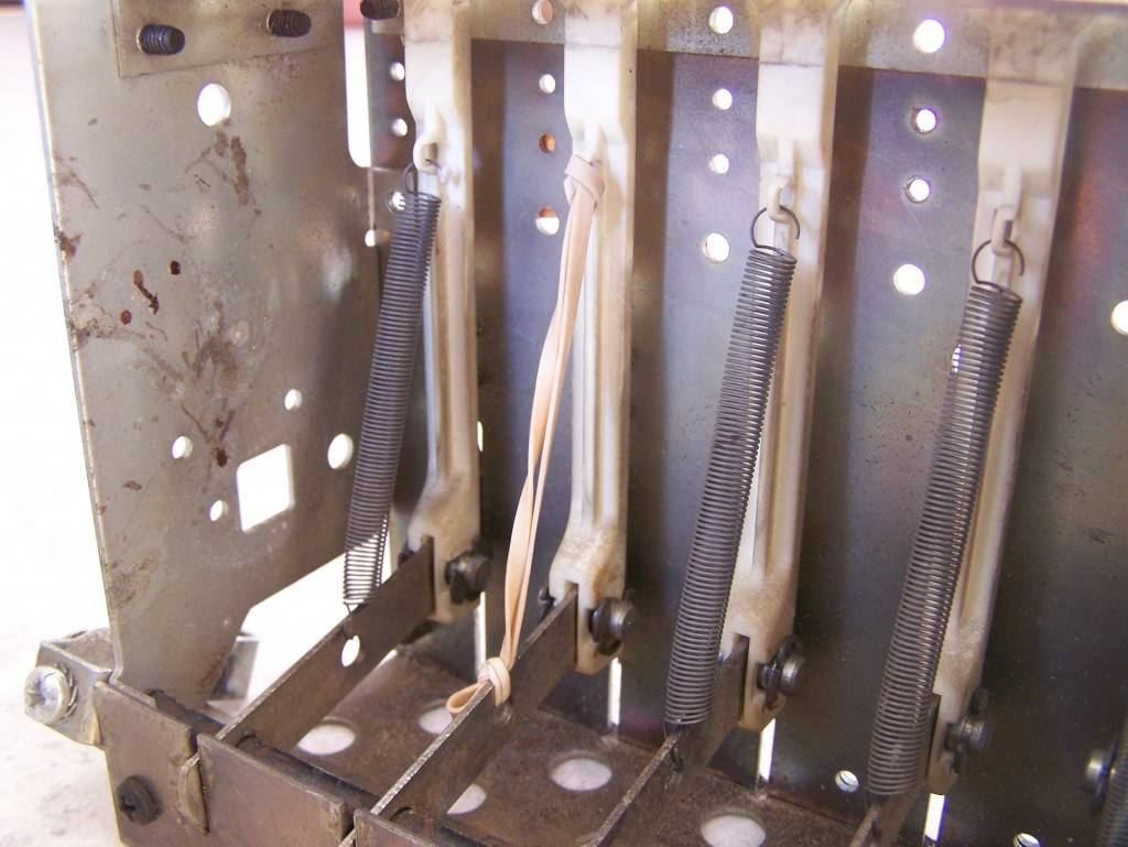
One of the Drop Targets was missing a spring. I managed to replace it with a rubber band. 😀 It works pretty well, and eventually I’ll buy a real spring. Or at least I like to think I will. 😛
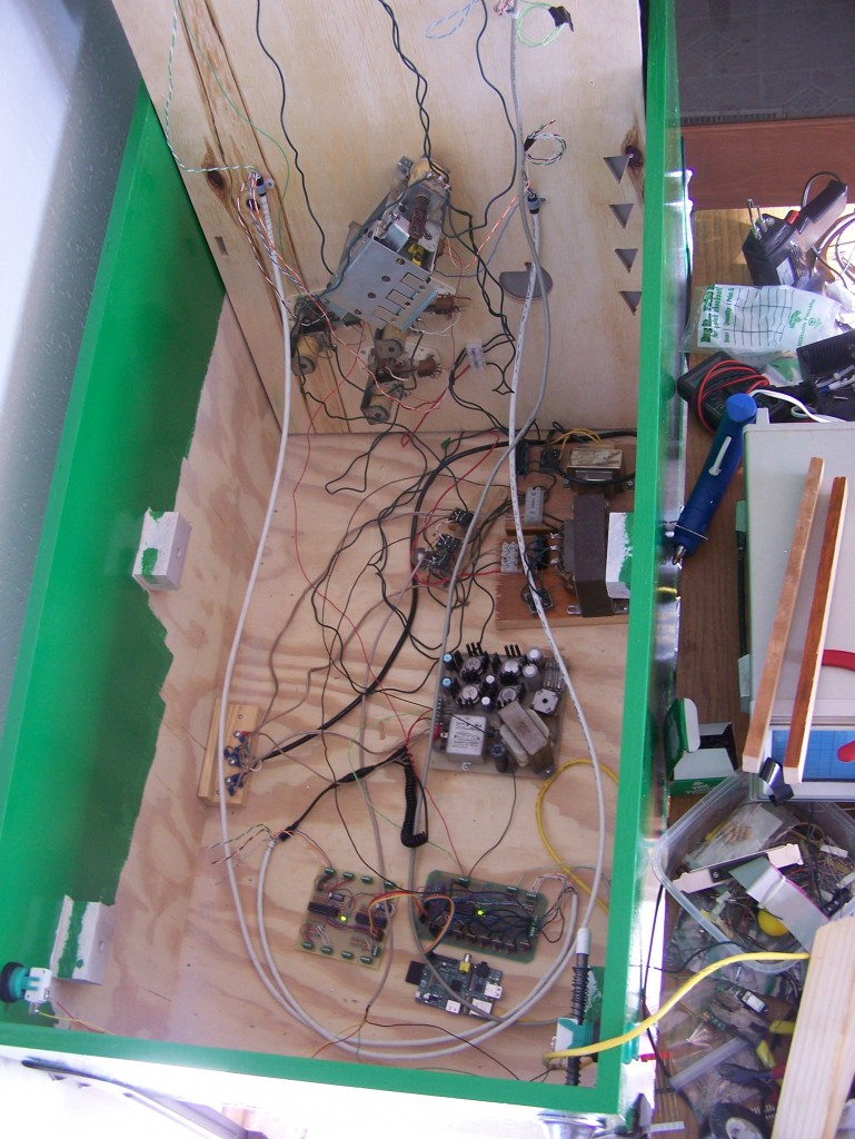
Here’s the cabinet so far. LOTS OF WIRES! 😀
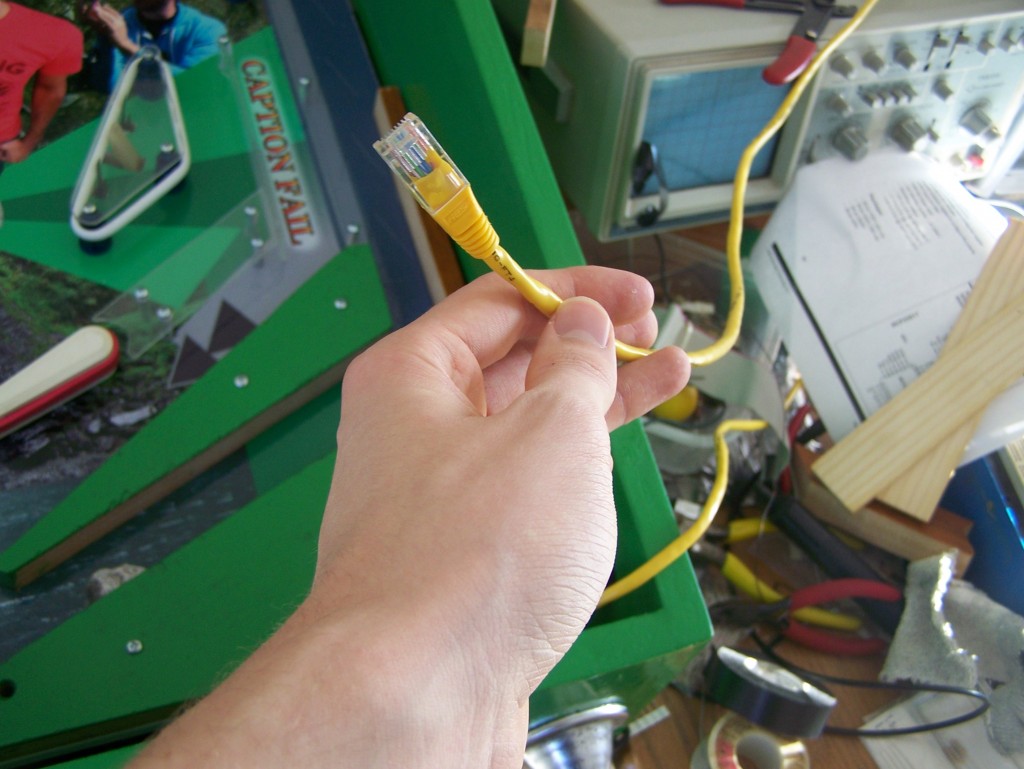
I think I may have the world’s only Ethernet enabled pinball machine. 😀
But seriously though, it’s the easiest way to diagnose problems on the Raspberry Pi.
I’ll install a jack eventually, but for now, I like to think of it as my pinball machine’s umbilical cord. 🙂
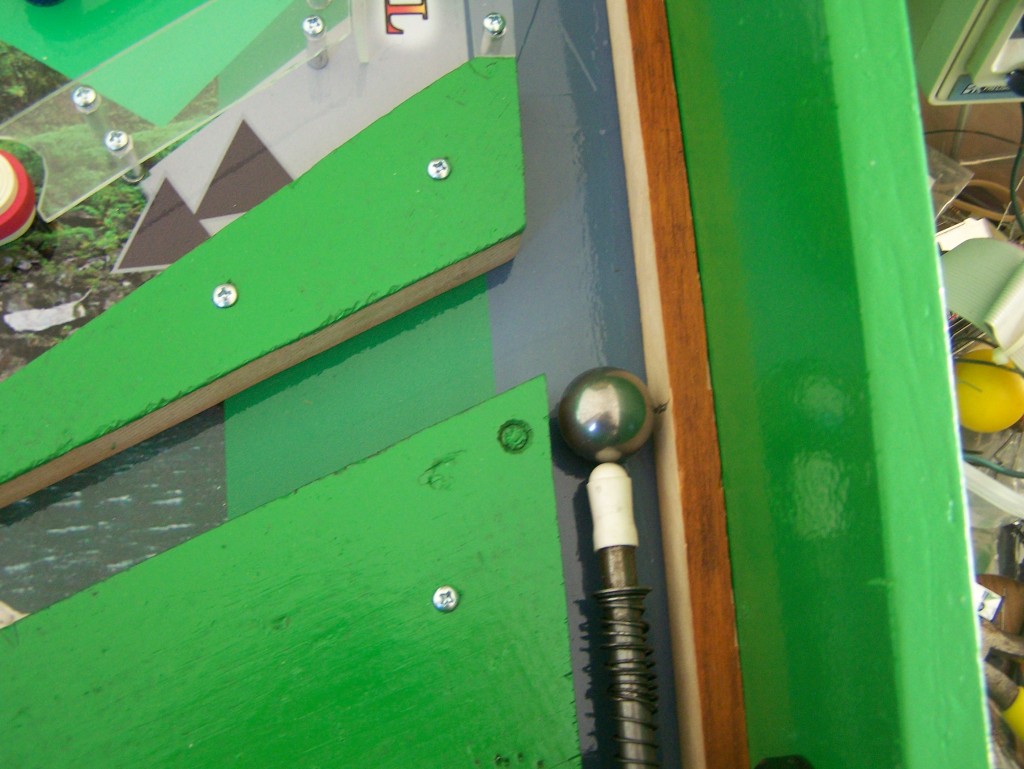
Here’s the ball, all ready to go! =D
Most of my rails and stuff are made out of 3mm acrylic plexi glass, held up by custom cut aluminum spacers. It works pretty well, and so far seems sturdy.
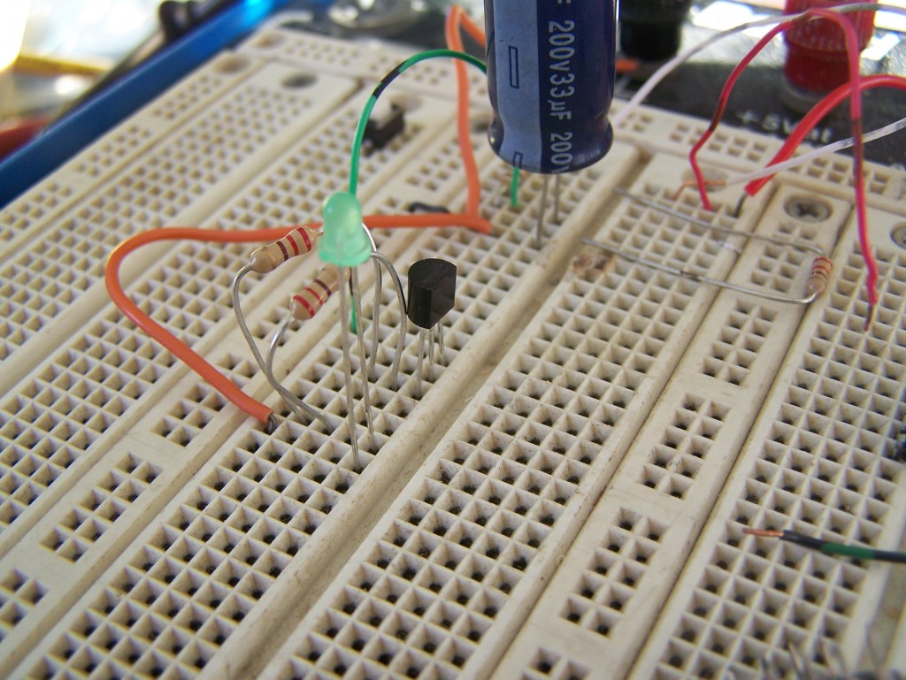
Here’s me prototyping some transistor circuits. 2n2222, baby!
Which means… that in a few weeks, we should get lights!! =D =D
That’s all for now, folks! If you want more real-time updates subscribe to my twitter. @marktbaldridge
Hi there. Love the project. I am a complete novice to Python and was helping you could give me a pointer as to how the io is working so well.. I am looking to convert a tomy American pinball using a pi and simple inputs to add a multiplier etc and some custom sounds etc. any snippets would be appreciated
Rick
Hey, Rick! So in this post I described how I had to re-design the “brains” of the pinball machine. Basically, something needed to run in a very fast loop, checking every input to see if it had changed, and then respond to that input. Basically running to every switch to ask “hey, are you on?” and if so, firing a solenoid, if not, moving on and asking the next switch. While somewhat primitive, this system does work well in principle. The problem was that if I ran such code in Python on the Raspberry pi, the code was far enough removed from the hardware that it would miss signals.
To solve that problem I switched to using an Arduino which has no operating system, and thus runs only my code. In so doing the entire loop ran hundreds (maybe thousands?) of times every second, and caught every input perfectly. The Arduino is only 16Mhz, but when you have every instruction of a processor to yourself, you can get a lot done in a hurry.
As to game graphics and sounds, I never really got that far. It is the next step when I begin working on the pinball machine again.
Hope that helps. 🙂
Hi, i love your project, i see now it could be some old, because i see the date was 2012.
My idea is to make a customized pinball like you, and i was wondering if you could publish the schematics or source of your control boards, that will be pinballtastic for me, because of my lack of knowledge with electronics.
Very nice project, let me know if you publish the schematics.
Nice, nice work
Thank you
Eloi, some of this is referenced in my previous posts, but I did send you an email with more detailed explanations of how to get started. 🙂